Table of Contents
The Omni Chicken
A Raspberry Pi-powered three-wheeled omnidirectional, line following, obstacle avoidance and obstacle tracking robot. Built with love and C.
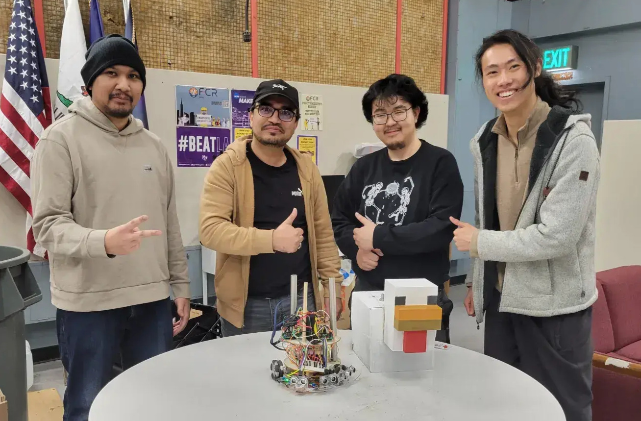
Meet the team
While we are all programmers, and this is by all means a programming computer science course, we all specialize in certain aspects. This is why I strongly believe we worked so well together because we complemented each other's skill sets and specializations.
- Shoaib Perouz (GitHub) - mechanics/electrical engineer
- Yuquan Xu (GitHub) - 3d modeler/designer
- Bryan Yao (GitHub) - physics/calculations
- John Carter (GitHub) - programmer
This write-up was co-authored with the group as a whole, with individual sections written by those who specialized in those areas.
But why?
This all started as a group project for our Embedded Linux programming class by SFSU's best professor, Robert Bierman! We got to work by brainstorming a bunch of ideas for this robot, specifically on the type of movement we would use, and some of the more notable ideas were:
- 4-legged spider
- bipedal walking humanoid
- two-wheeled self-balancing humanoid
- crab
- snake
We finally settled on a three-wheeled omnidirectional robot HEAVILY inspired from this video by maker.moekoe:
This design was not only fairly simple (at least on the surface) but also never been done in our Professor's class yet.
You see, while the Professor planned to give extra points to those who could finish the fastest, there were some things that I was wary of if we were to go for speed:
- The track was laid out in a cloth, making grip difficult (especially with our wheels)
- The ground was also uneven, with too many bumps and debris that may launch our bot up if we go too fast - and lose track of the line
- and lastly, there was another group, a VERY VERY talented group who were aiming to have the fastest time.
And while I'm confident in my team and my abilities, attempting to be the fastest just posed too many uncontrolled variables. So we changed direction...
Instead of being the fastest, we chose to be the flashiest! The silliest, yet still functional robot. We wanted to make an impact, but not by being the fastest, but by just being different. So we stuck to our 3-wheeled omnidirectional design, and started coming up with ideas on the shell and how we can make it even cooler!
I also learned later on that the Professor gives extra points for creativity!
Design
Ambitions were high for our initial design. The main idea we had to work around was a three-wheeled omnidirectional robot. Here are some of Yuquan's sketches:
This is the very first instance of the bot that we drew up in class. Aptly nicknamed the omni-cake, because of the sandwiching components in between layers. This served as an initial design idea, along with where to mount the sensors, motors, pi and its components. You can also see how we started drafting ideas on how it would traverse.
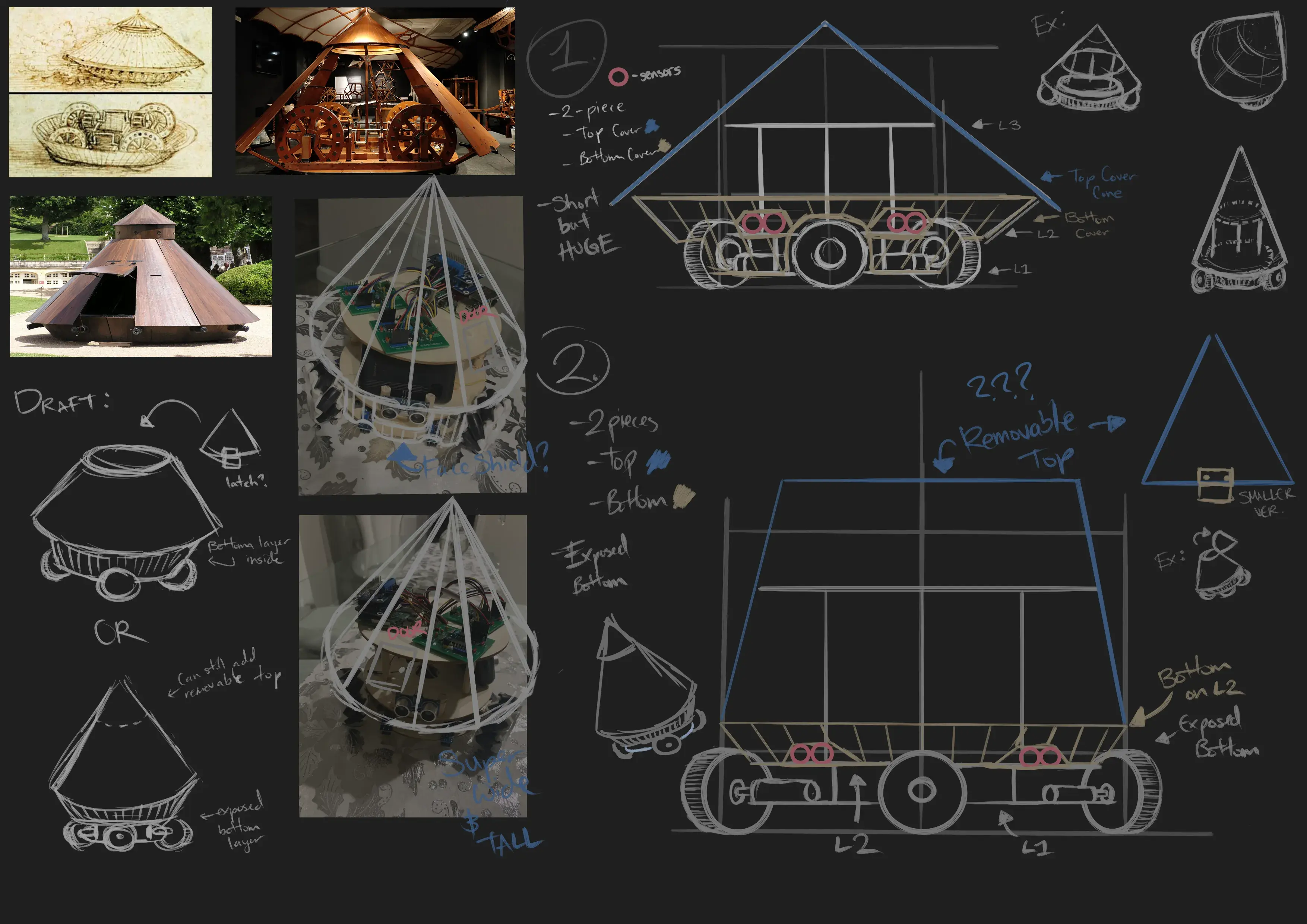
As you can see, we initially thought of going for a Da Vinci Tank, which seemed like the most ergonomic and simplest design. It was balanced and could fit all of the components pretty neatly.
Another suggestion, by yours truly, was to make it similar to the shape of a... Yeah, you'll see here in a moment.
Note the top left one, yeah, that was my suggestion. And as you probably already know we did not choose that.
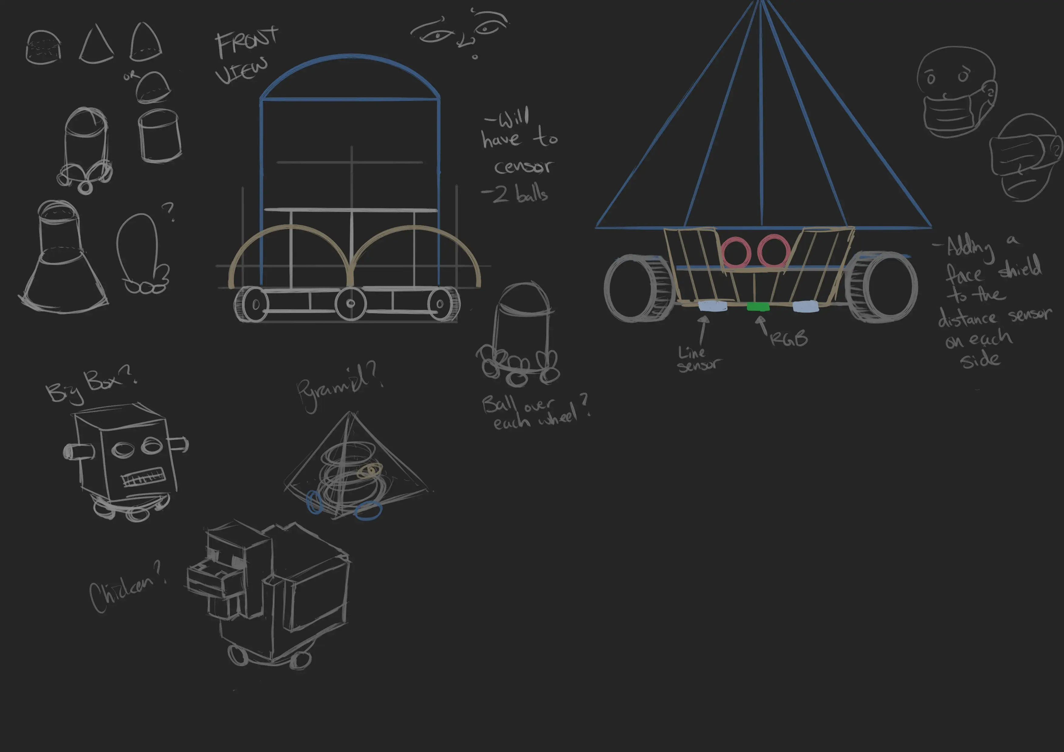
However, from Yuquan's extra doodles, he created something that caught our eye: The Minecraft chicken (and also the robot head). An amazing and hilarious idea because of both the recent popular Minecraft movie and the arguably even more popular dumb chicken jockey meme. This has now become our main design goal, and something we want to fully commit to.
Shoaib didn't know we were serious about the chicken until we were a month into our project XD
Version 0.5
Our very first build, all parts were sourced by Shoaib and assembled by him. His design was meant to be a prototype but was ultimately used as a base for the overall robot. Note the mechanum omni wheels. Because they weren't true omnidirectional wheels, they were a major headache for us. It's a cute little thing, though.
Version 1
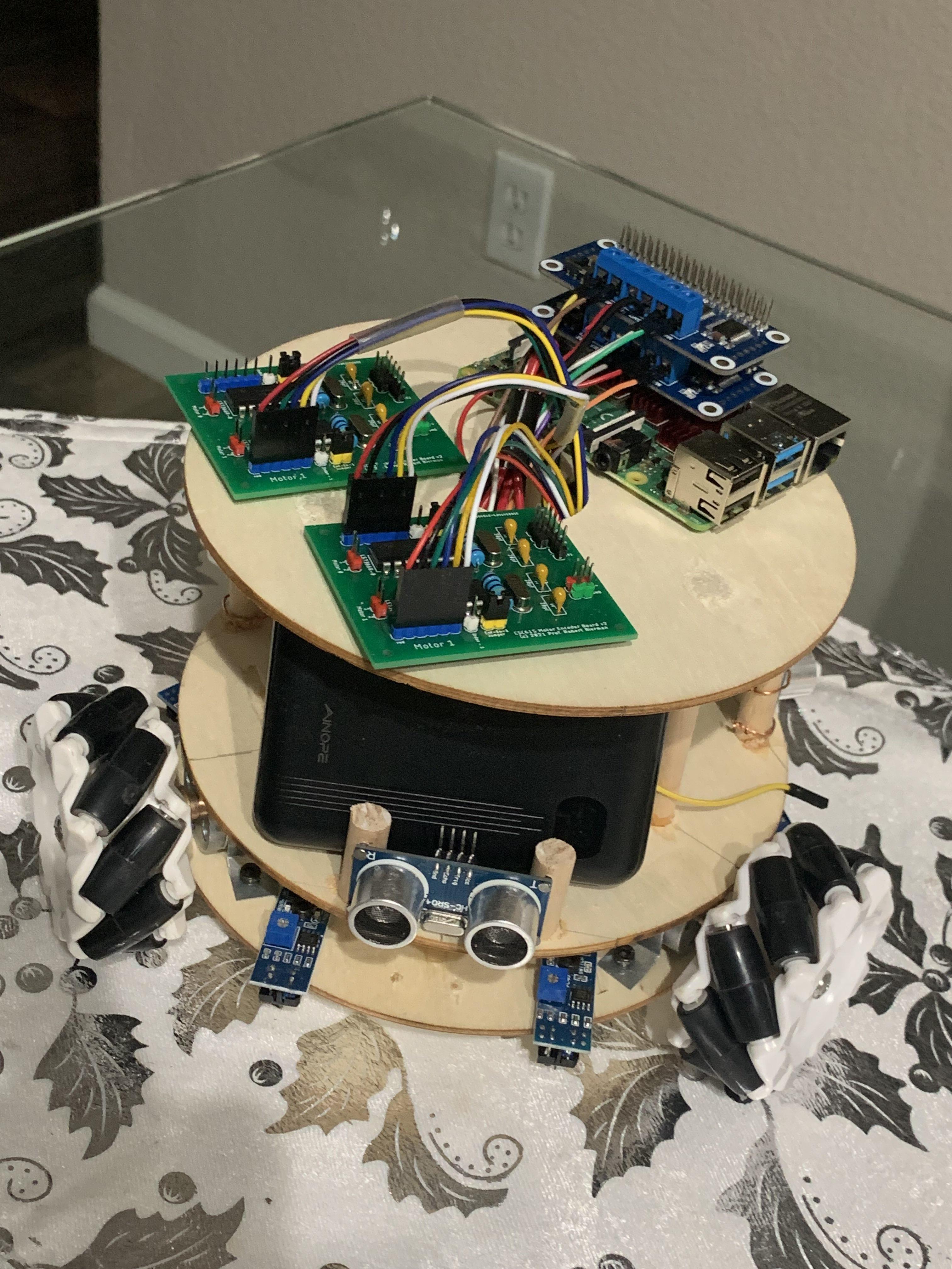
Version 1, parts added by Shoaib to include the raspberry pi top plate, effectively making a cake. This 3 plate design carried us pretty far, but it started to become pretty heavy and constrained in terms of space and structural rigidity. So we had to get a little creative in terms of how the components and wiring it all up.
True Omni-Wheels
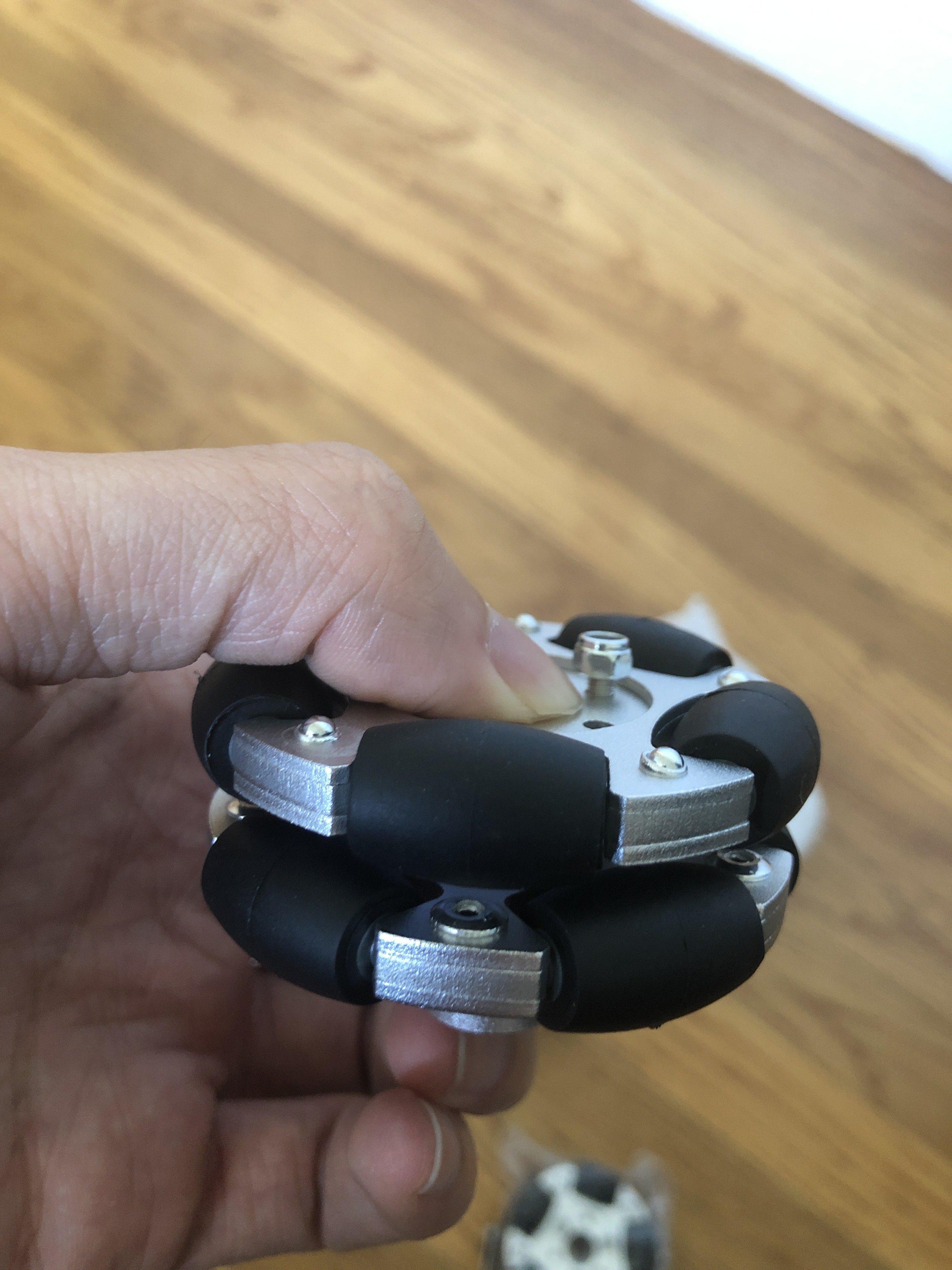

Bryan managed to find some true omnidirectional wheels, sourced from robotics supplier, which initially cost ~60 bucks for three wheels. But because of the tariffs, the price ballooned to 100 USD. They were at least kind enough to also provide 3D models of them.
3D Printed Chicken Body
Professor Bierman gave every group a chance to have 3D parts printed. And because we're pretty damn greedy, we took up a decent amount of both material, and time to have our LARGE chicken body printed. The total cost of the print was around ~$30. But Professor Bierman gave it to us for free! Which was honestly a pretty sweet deal considering how big and how long it took to print.
Version 2

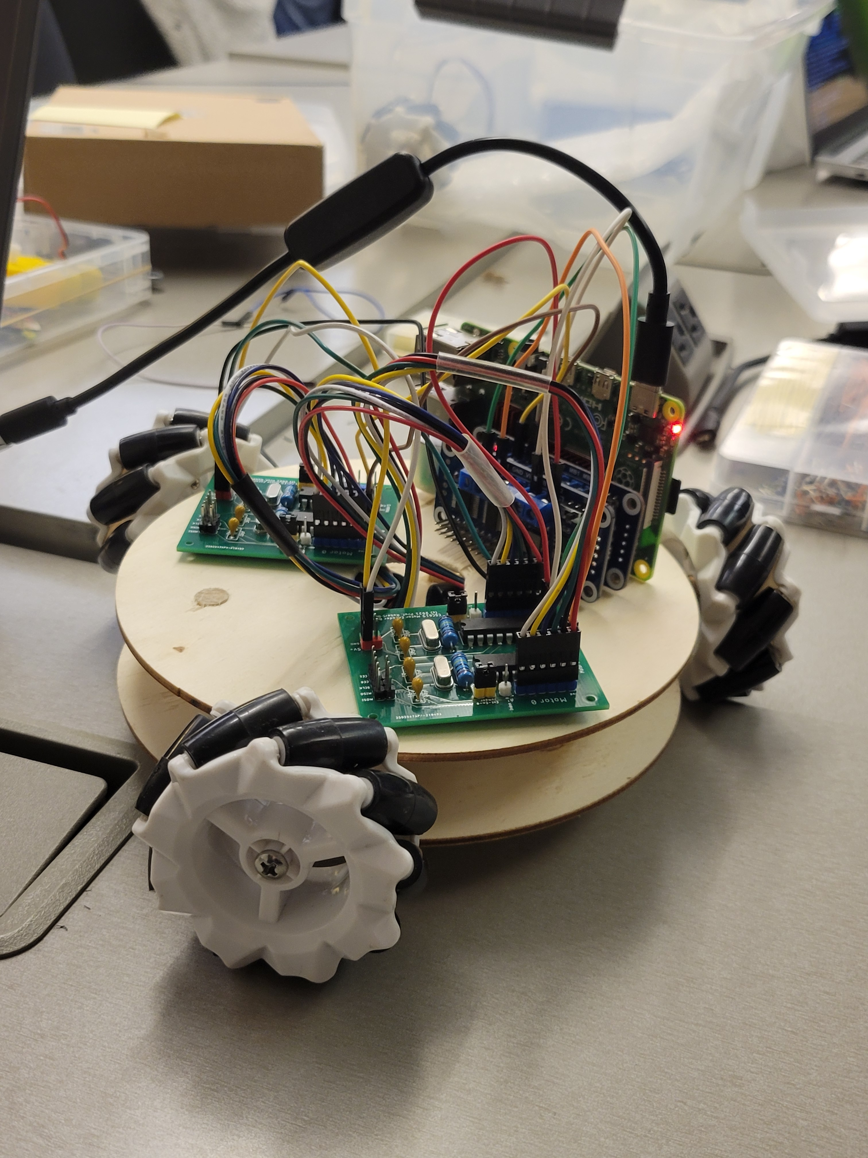
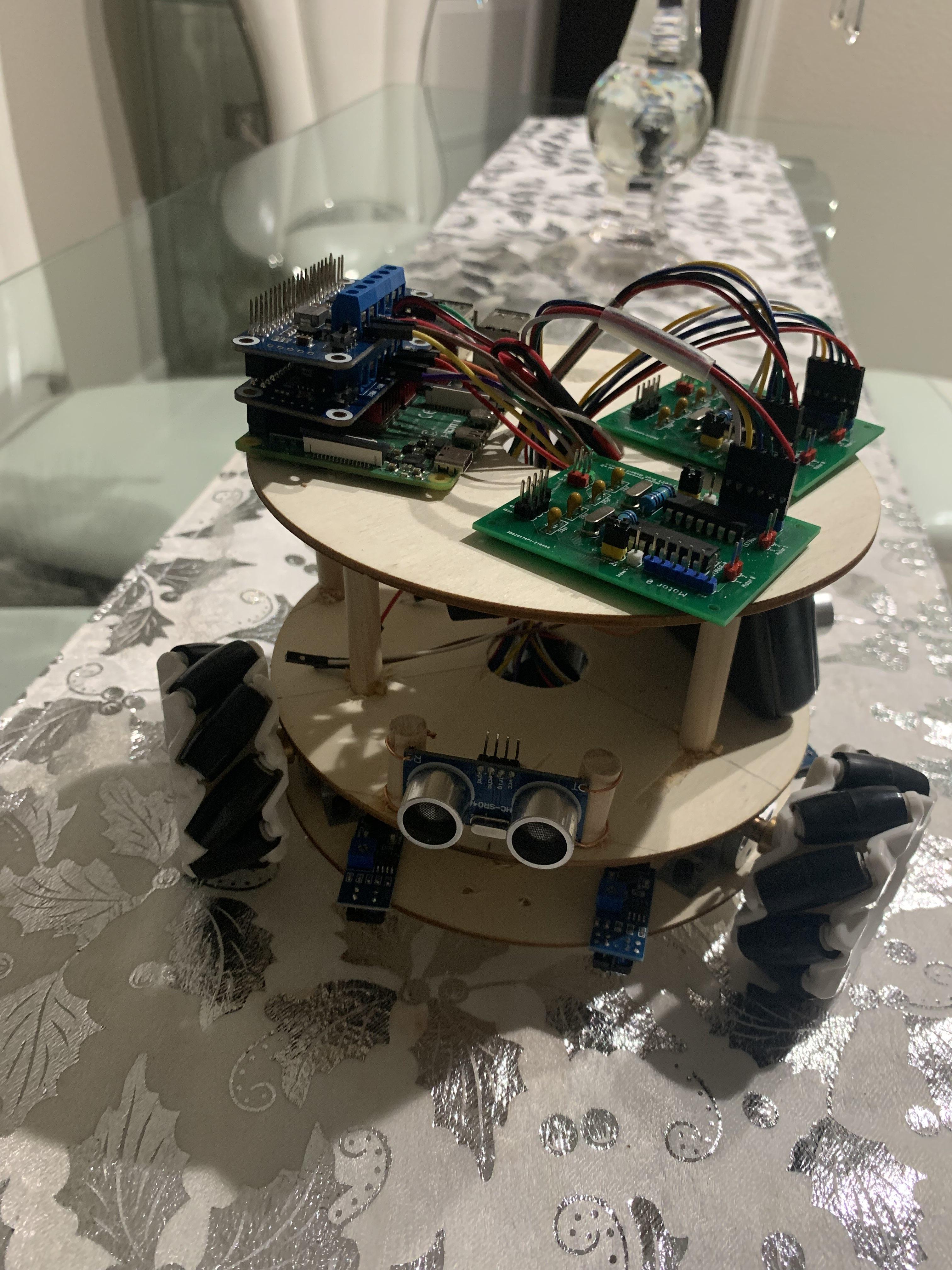
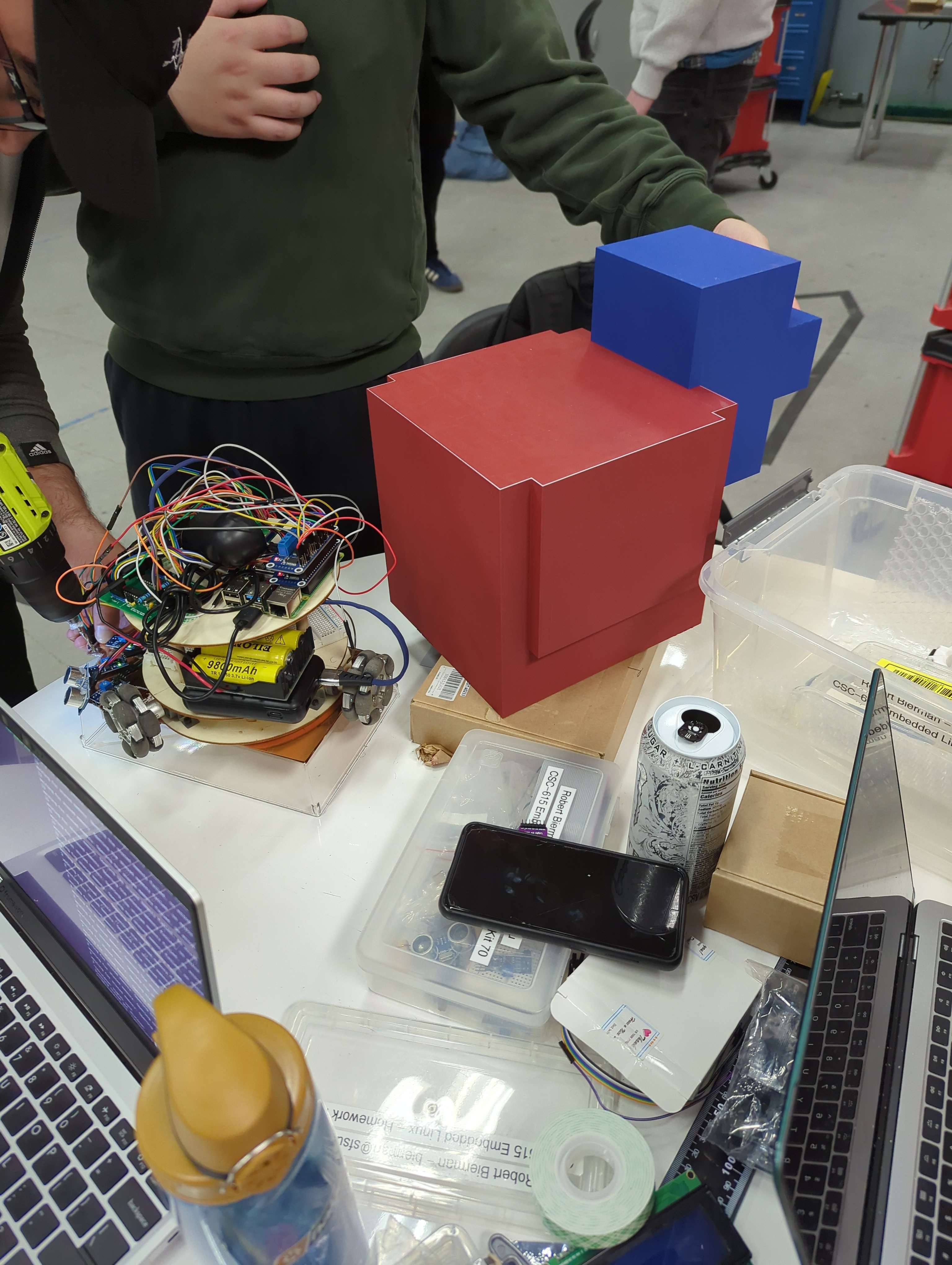
Now... I know what you're thinking... That's a whole lotta wires! But trust me, it's completely functional. Cable management is not our specialty, but cleaning it all up could come later. At this point, the bot was completely functional; it was missing some optional features that I wanted to implement, but it could line-follow and avoid an obstacle at this point in our project.
I have to admit though, it did bring up a lot of headaches down the line. Mainly because of our exotic setup. This is a draft of our initial hardware diagram - excuse the errors, we drew this haphazardly.
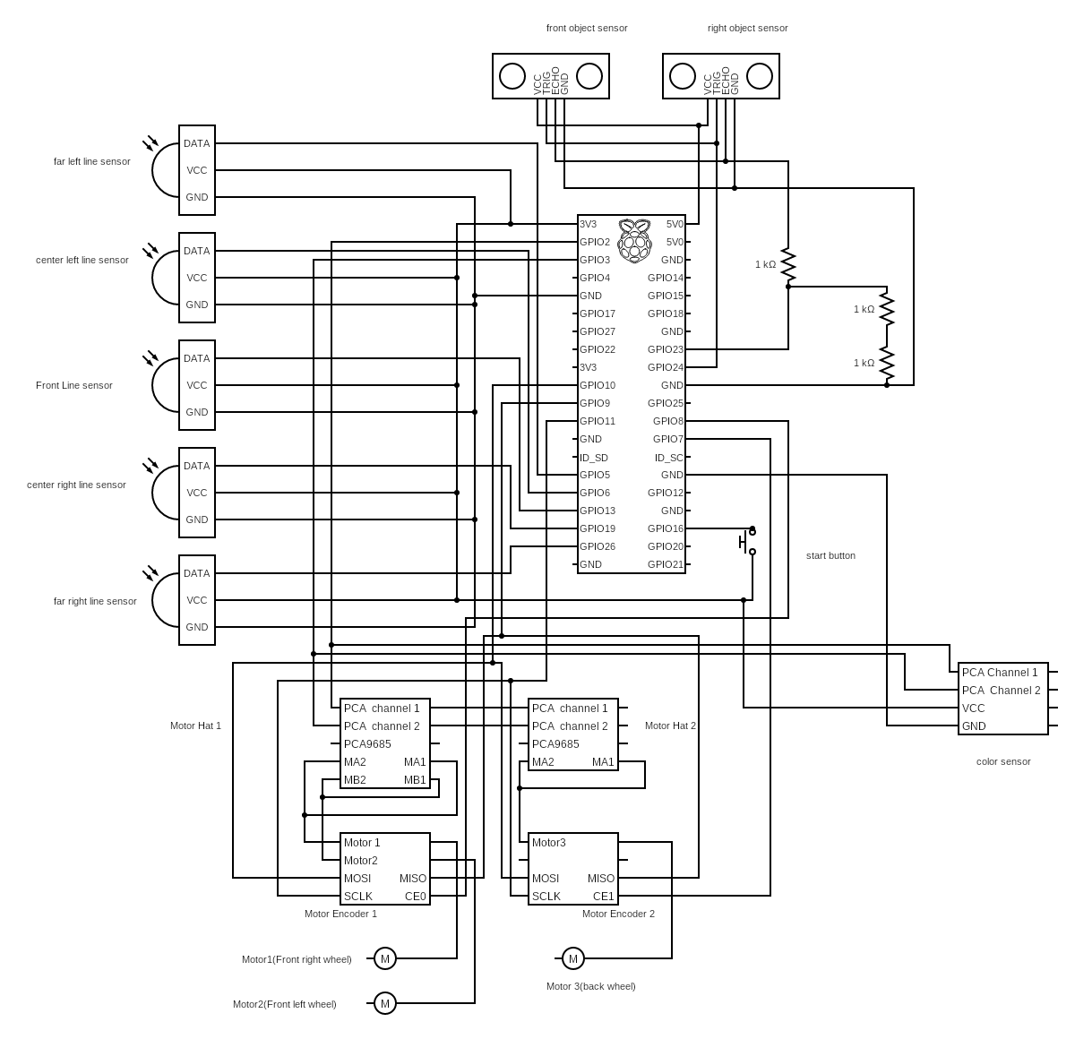
As you can see, it's not the prettiest in terms of diagramming, we did manage to clean up a lot of it towards the end - at least shortening the amount of jumps wires would need to take by directly connecting them to the GPIO pin-out. But the hardware needed to communicate with Pi somehow right? And while it's ugly, it works - which is what matters the most, considering our deadline is coming up.
The Final Version

The crème de la crème of all the versions, the completed robot that ran the full course. A sight to behold to say the least. It ran damn near perfectly in terms of the line-following, there were some hiccups in the obstacle avoidance/tracking, but that was due to our sensors failing or giving us horrendous readings.
We did have to make a couple of concessions. First, we sadly couldn't use the 3D printed body Prof. Bierman printed out for us. Luckily, Yuquan had made a spare body crafted out of used Amazon shipping boxes - it proved light and rigid enough to install the 3D printed chicken head.
Physics
Physics was mainly handled by our resident genius, Bryan. He came up with not only the math needed for vector direction control, but he analyzed and took direct inspiration from actual research papers so we can have proper 3-wheeled omnidirectional traversal. He'll take it over from here.
Preface
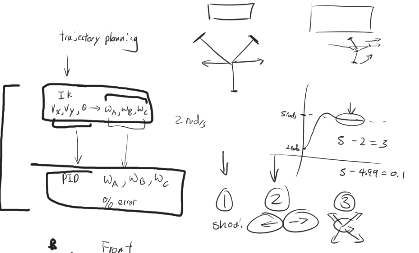
During my research, the general control scheme goes as follows:
trajectory planning -> inverse kinematics -> and then to PID/error control. This general control scheme is supported and outlined in these research papers.
Intro
But why? I started on $IK(Inverse\hspace{5px}Kinematics)$, because that is the most part foreign and tricky part about the control scheme. The trajectory planning part just seemed like vector math which was something I was familiar with. The IK the was function was this first step of this crucial interlayer of going from digital controls to physical elements.

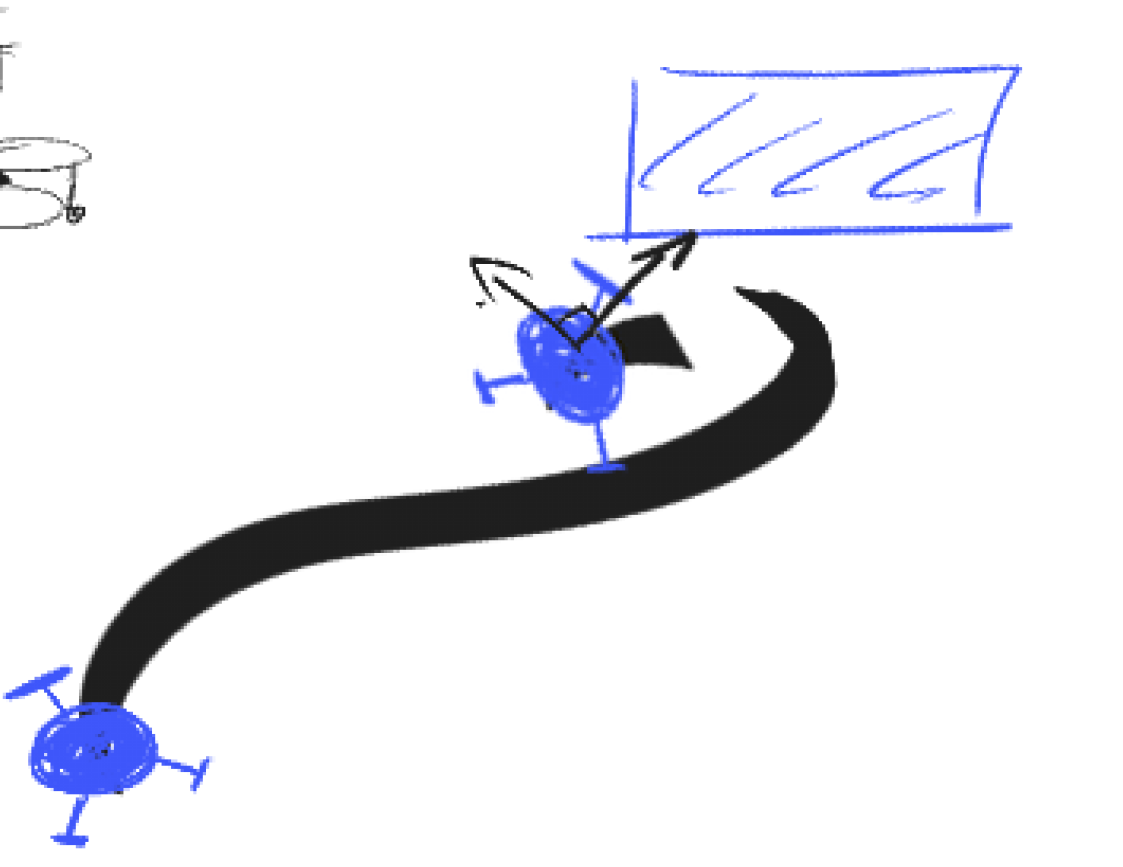
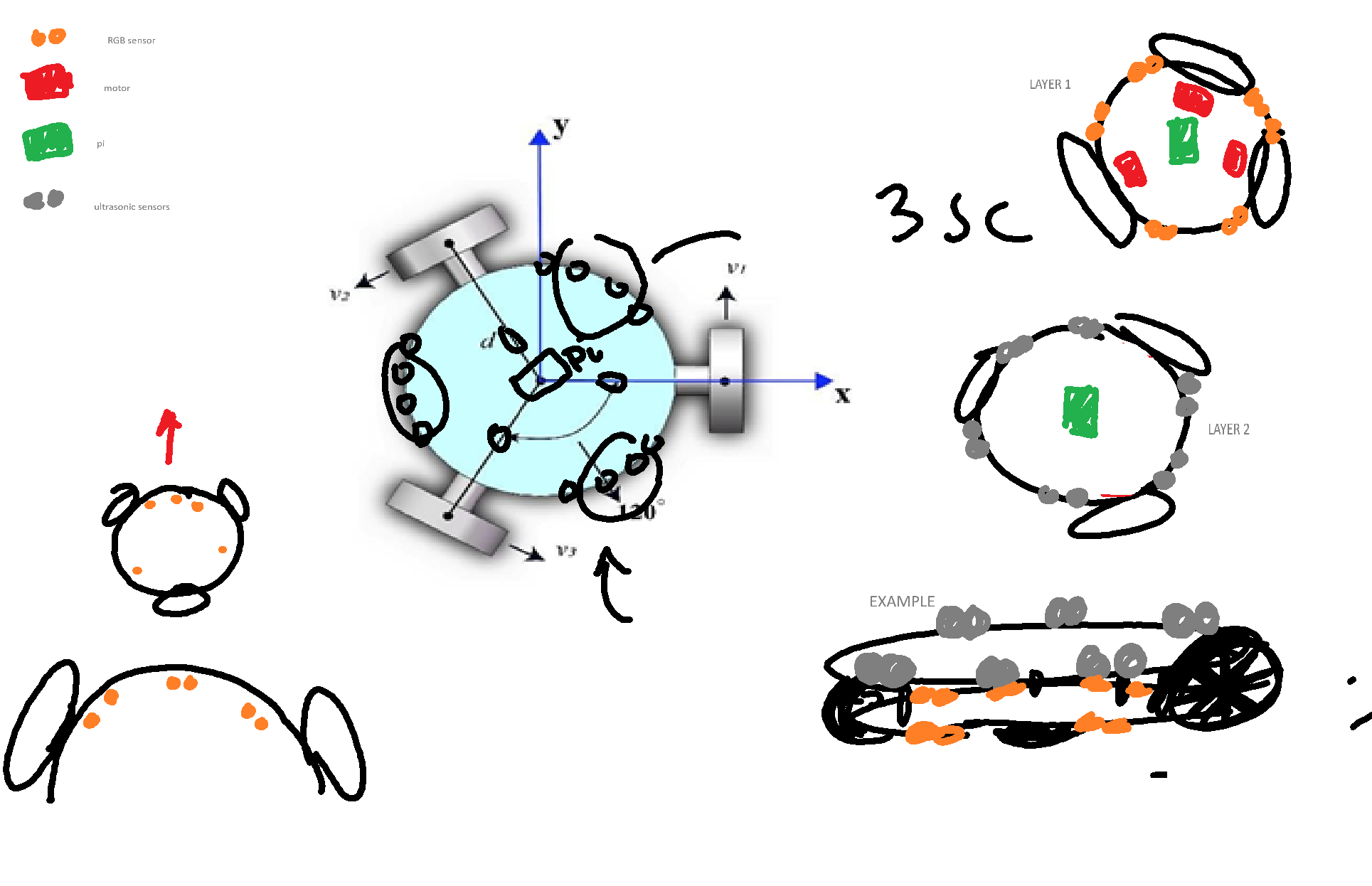
These are initial sketches for obstacle tracking. Our initial idea was to essentially encircle the obstacle by strafing around it, keeping the robot's front facing the object the entire time. On the surface, it sounds pretty easy, right? Just set a point in front of the robot and traverse around it. But in practice, it's not so easy...
The original idea was to simply, trace a circle around the object with $X$ radius away from the center of the car. For that specific part, we needed Inverse Kinematics.
Inverse Kinematics
In simple terms, it is the conversion from $(X, Y, \theta)$ coordinates into angular velocities of the motor (AKA, how fast the wheels should spin). Which allows us to control the omni-directional movement of the chicken.
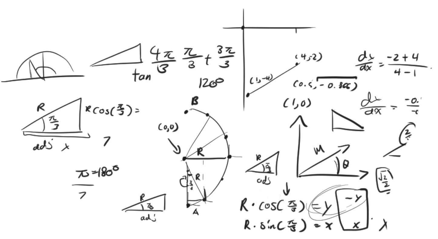
For Example:
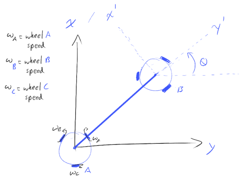
From the image, to traverse from point $A$ to point $B$ with a desired rotation, to illustrate that we break it down to the components of $X, Y$ and $\theta$. Where the $X$, $Y$ is the distance the distance and $\theta$ would be the rotation. Thus, the $IK$ gives us the angular velocities: $ \omega_A$, $ \omega_B$, $ \omega_C$ we need to achieve point $B$.
TLDR: We go from a distance & rotation to the speeds the wheels need to spin at.
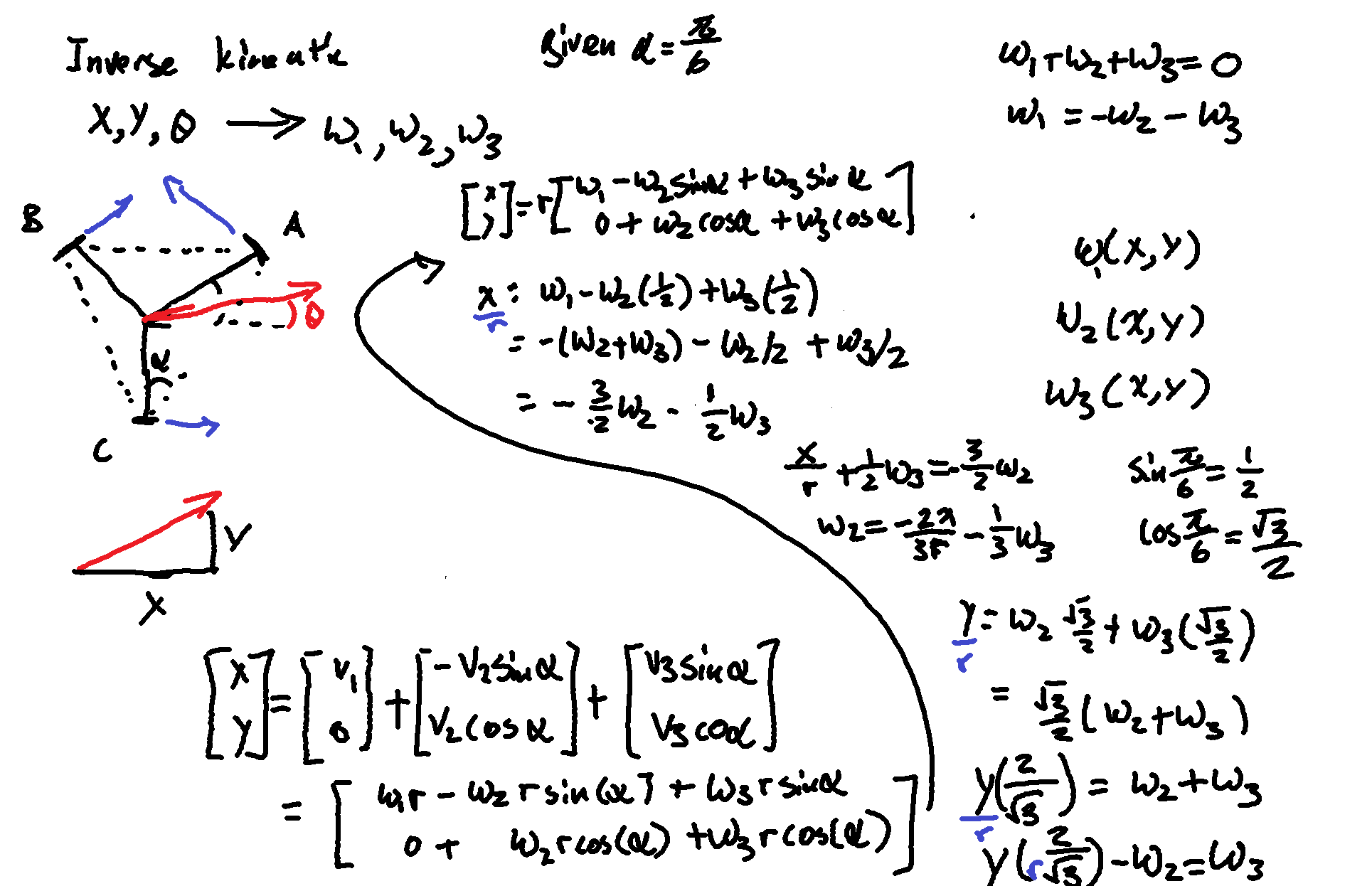
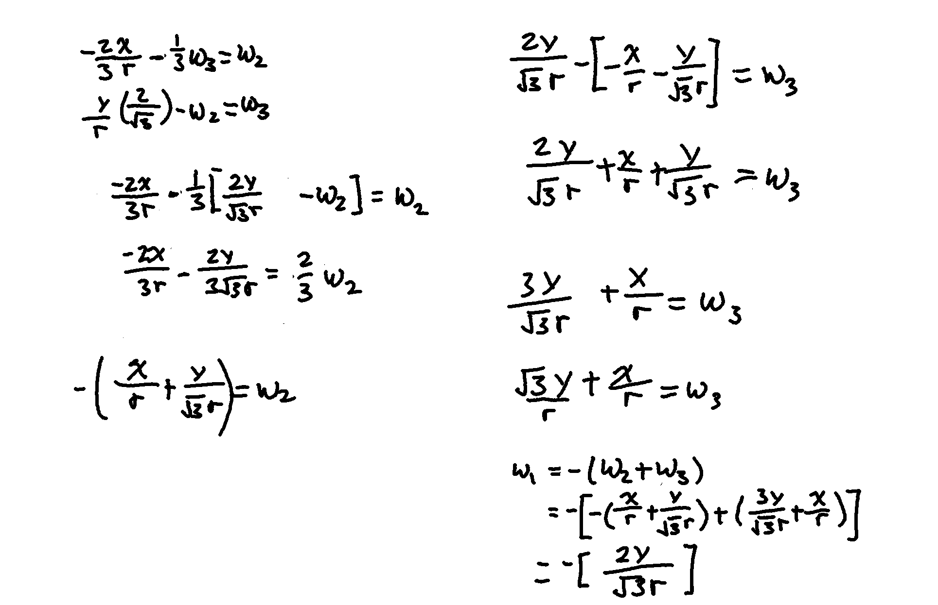
This gives you an idea of how the inverse kinematics is calculated but WARNING these sketches/formulae are our draft versions and do not reflect our final matrix calculation for the $IK$.
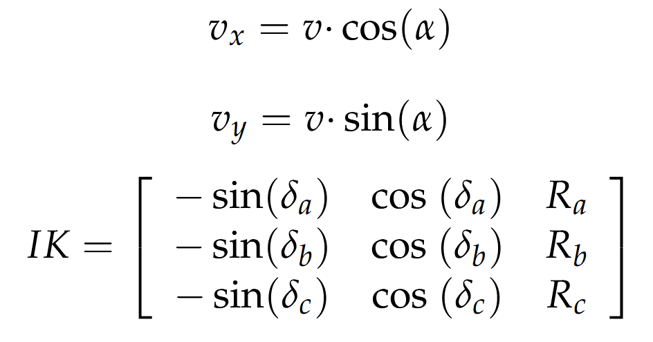
This is the formula taken adapted from this research paper. If you want to learn how this formula was derive check out the motion system of the mobile robot APR described in Moreno et al.
First we set
$$ \delta_a = 30^{\circ}$$
$$\delta_b = 150^{\circ}$$
$$\delta_c = 270^{\circ} $$
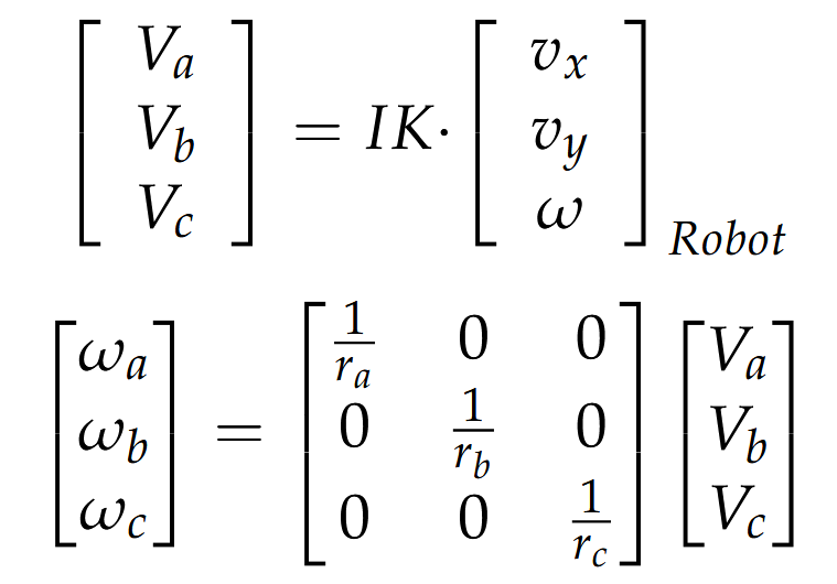
Then we multiply by the $X, Y$ and $\theta$ to get our velocities then recall that:
$$ V = R\omega $$
$$ \omega = \frac{V}{R} $$
Applying this to all 3 wheel, in the matrix notion:
Error Correction
The idea of the Error Correction is once we calculated the desired angular velocities the wheels should spin at, we then need to measure and compare that to the actual angular velocity of what the wheels are currently spinning at. This difference from the desired angular velocity and actual angular velocity is the Error. We correct for this Error using the PID (Proportional Integral Derivative) controller.
Simply put, PID corrects for change over time. There are values you can tweak to change how fast that is implemented. You can also tweak the behavior of the correction
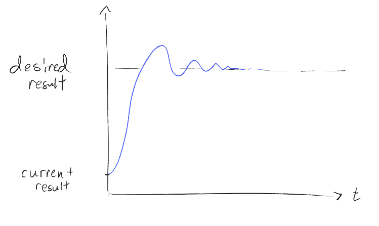
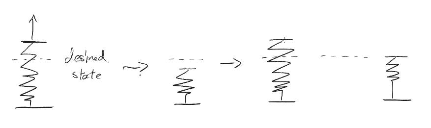
I like to think of the PID control as like a spring. As you release the spring from the stretched length, it will oscillate and eventually approach resting position. Similarly the robot/robotic arm can do this where it might overshoot a bit then needing to correct for this. But all of this can be controlled for by the $K_p$ , $K_d$ , $K_i$. Which you can think of as dampening and how fast it approaches the desired result.
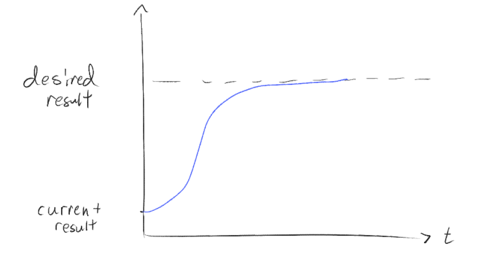
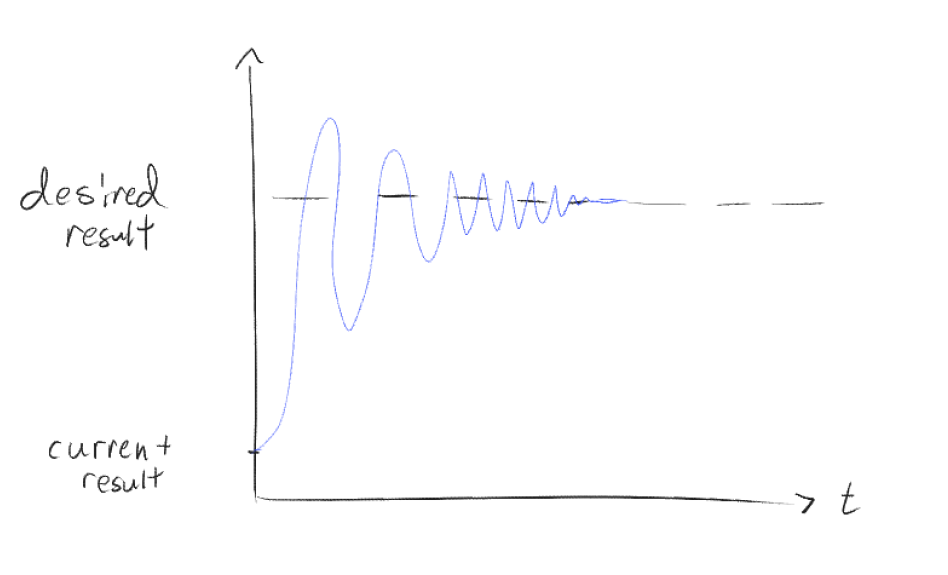
When tweaked, other variants of the graph might look like these:
Theoretical formula:
$$ \begin{equation} u(t) = K_p e(t) + K_i \int_0^t e(\tau),d\tau + K_d \frac{d}{dt}e(t) \end{equation} $$
Basically ripped straight from this video that explains it in great detail.
Motor encoder
The general idea is that we read from the motor encoder to get the amount of ticks, and from that we can calculate the speed of the motor - that is the value we are going to compare with the calculated $IK$ value.
An example of getting and reading the speed from the motor:
int lastCountA = 0;
#define PULSES_PER_REV 540.0
#define PI 3.141592654
#define WHEEL_RADIUS 6.5

for (int j = 0; j < 20; j++) {
    int resultA = readLS7336RCounter(SPI0_CE0);
    double revsPerSecA = ((resultA-lastCountA)/(4PULSES_PER_REV));
    double speedA = revsPerSecA (2* PI * WHEEL_RADIUS);
    printf ("Count: %d, Revolutions: %f, Speed: %f, delta: %d\n",
            resultA, revsPerSecA, speedA, resultA-lastCountA);
    lastCountA = resultA;
    sleep (1);
}
Trajectory Planning
John, gave commands devising semi-circular orbiting trajectory for the chicken. This will not only make it more realistic according to Minecraft cannon when a player holds a seeds but it provides the added benefit of being as quoted
"it'll look sick as f*ck" - John
as described.
To achieve this, we created a trajectory by having a half circular path with sub-divided point to be later interpolated
Note: Interpolation is the generation of path/function that would cross the to points.
Here is my schizo drawings for the diagram and planning phase
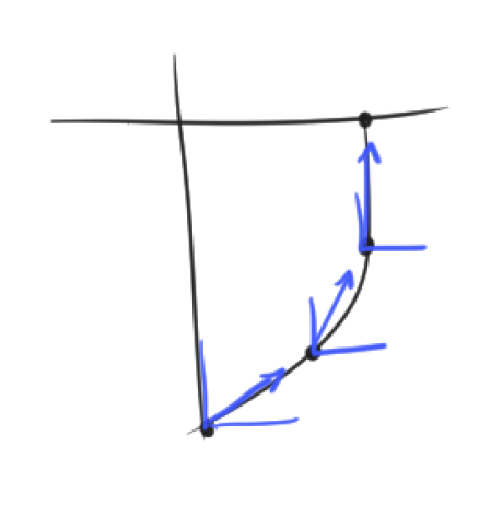
Without overcomplicating it all, I simply generated an arc path from a start position and target position, then traversed using time-based interpolation along a continuous curve around the object. Each point generated by this trajectory feeds directly into the inverse kinematics equations, where the $(X, Y, \theta)$ coordinates get converted to individual wheel velocities using the matrix calculations I detailed earlier.
I chose this method because it seems the most straight forward for our use case. And now instead of boring straight-line pathing, we now have dynamic, arcing trajectories that make the robot feel more unique and visually COOL. And that pretty much concludes the physics portion, the most tedious and arduous portion that involved the most research and gruelling testing (to fine-tune sweet spots).
The Code
Now back to me (John) for the juicy coding section which was handled mostly by me as part of partitioning our work load. Note that I consider myself a huge programming noob which is especially true with C, so I won't be able to explain a lot of the technical stuff in the best way, but I'll try my best.
A couple things to get out of the way first. My design philosophy for how I wanna go about this boils down to:
- Robust: kill on panic, handle errors gracefully, zero (no promises) memory leaks.
- Modular: plug and play, be able to use previous assignments, code can operate independently of one another.
- Readable: code should be able to read quickly and understand code with minimal documentation
- Easily Modifiable:
- Flat directory structure: no directory hierarchy
- Can jump around relatively quickly within NeoVim
In terms of the architecture, I've made an initial diagram to help when we first started to program it:
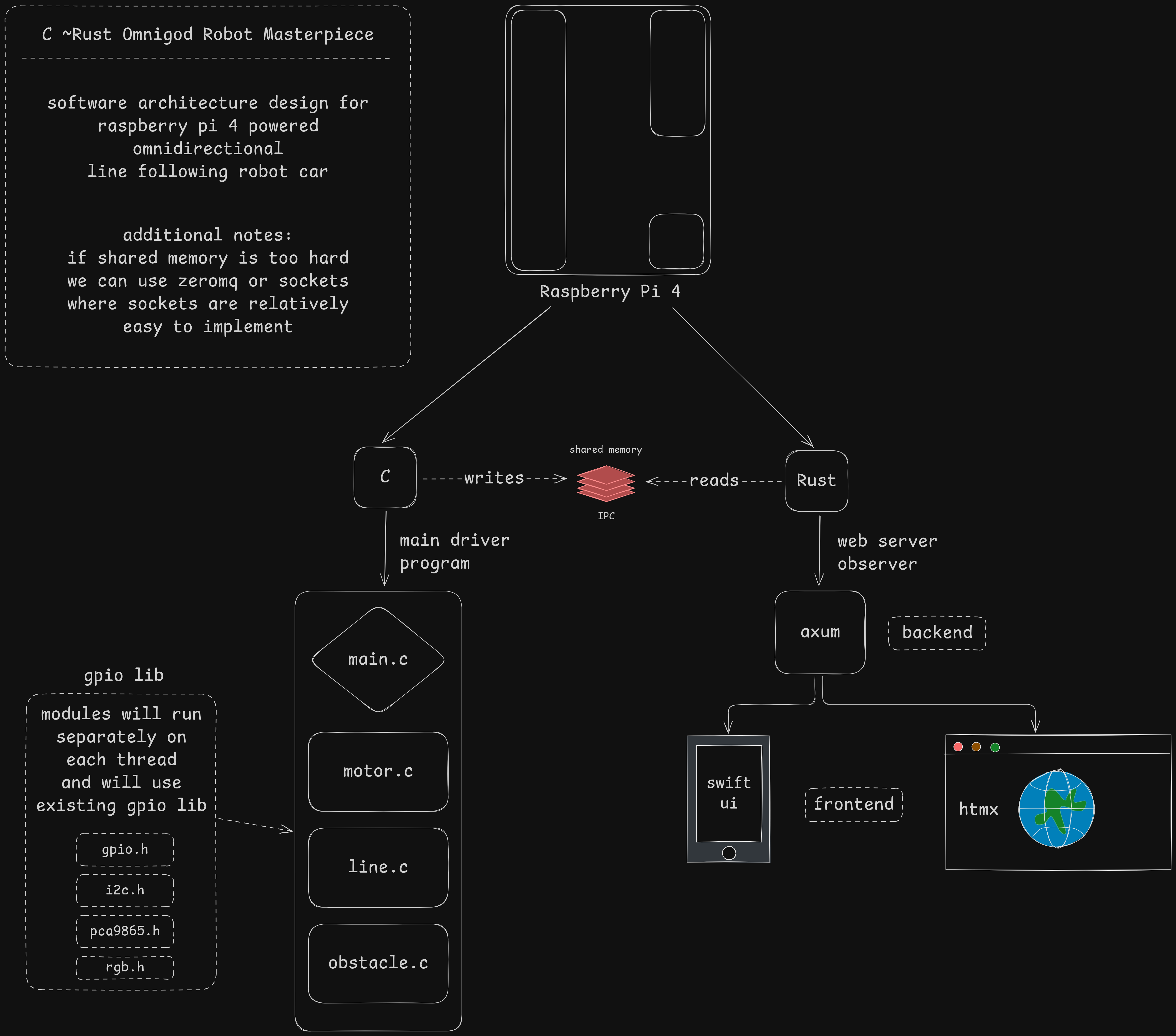
Note: This diagram is from an older design that's missing a decent amount of 'modules'
The C program, nicknamed omnibot, manages the whole thing, the control surfaces, sensor reading, and the whole shebang. That Rust part you see will be touched on later.
GPIO Library
My first goal was to create a robust GPIO library based on a Raspberry Pi DRA example I've been using it from my previous assignments. Modifying this, I got rid of all the preprocessor macros - mainly because they were quite frankly unreadable for me in that syntax, which is rich coming from a Rust enjoyer.
Wrapping those macros into more useful functions:
extern int setup_gpio();
extern int terminate_gpio();
extern int toggle_gpio(int gpio_pin); // helper function for quick toggling
extern int set_gpio_level(int gpio_pin, int gpio_level);
extern int get_gpio_level(int gpio_pin);
extern int set_gpio_pull(int gpio_pin, int pull_level);
Now... I'm gonna be honest, it does not completely look like above, and we currently have some redundant functions like set_gpio_inp/set_gpio_out. And yes, I can probably switch those right now... but I haven't done that here yet, and only did it for my Rust rewrite.
In terms of readability, I kinda wish C had the pattern matching Rust had. But For the sake of not overcomplicating the code, I just wrote a utility functions like validate_gpio_pin for robustness(?).
Also, I did not realize I wasn't supposed to be using /dev/mem, which requires sudo level access and manually specifying the GPIO address. After learning from this pi forums post, I switched to /dev/gpiomem, and got rid of a function that would look for the device address.
From this:
int find_gpio_addr() {
    // cat /proc/iomem | grep gpio
    // ....
}

int setup_gpio() {
    int gpio_addr = find_gpio_addr();

    if ((mem_fd = open("/dev/mem", O_RDWR | O_SYNC)) < 0) {
        // ...
    }

    gpio_map = mmap(
        NULL,                   // Any address in our space will do
        BLOCK_SIZE,             // Map length
        PROT_READ | PROT_WRITE, // Enable reading & writting to mapped memory
        MAP_SHARED,             // Shared with other processes
        mem_fd,                 // File to map
        gpio_addr
    );
    // ....
}
To:
// no longer need find_gpio_addr
int setup_gpio() {
    if (fd = open("/dev/gpiomem", O_RDWR | O_SYNC) < 0) {
        // ...
    }

    gpio_map = mmap(
        NULL,                   // Any address in our space will do
        BLOCK_SIZE,             // Map length
        PROT_READ | PROT_WRITE, // Enable reading & writting to mapped memory
        MAP_SHARED,             // Shared with other processes
        mem_fd,                 // File to map
        0                       // GPIO address location
    );
    // ....
}
Which felt cleaner, and overall much safer in terms of giving the program sudo level access to /dev/mem.
Multi Modal
One of the architectural design decisions I came up with was to have multiple modes for not only the bot itself, but also obstacle modes, sensor modes, and traversal modes.
Switching between these modes was handled by a multithreaded terminal controller term.h that modified the shared memory struct. (I honestly don't know if this is a good idea, but it seems to work, so wynaut?)
Here are what they look like:
// 0 -> line following
// 1 -> obstacle mode
// 2 -> manual control
// 3 -> wander mode
int bot_mode;

// 0 -> obstacle tracking

// 1 -> obstacle avoidance
int obstacle_mode;

// 0 -> four sensor mapped logic
// 1 -> five sensor weighted average
// 2 -> two sensor simple mode
int sensor_mode;
Reading from Sensors
Reading from sensor data is multithreaded, and will continue while the main thread (where all the logic and mode handling is). Reading from sensors is pretty trivial, and making it multi-threaded is not that hard if I may say so myself.
// 0 - no
// 1 - yes
extern volatile int go_left;
extern volatile int go_right;
extern volatile int found_line;

extern volatile int obstacle_detected;

void *detect_obstacle(void *args);
void *detect_line(void *args);
Shared Memory
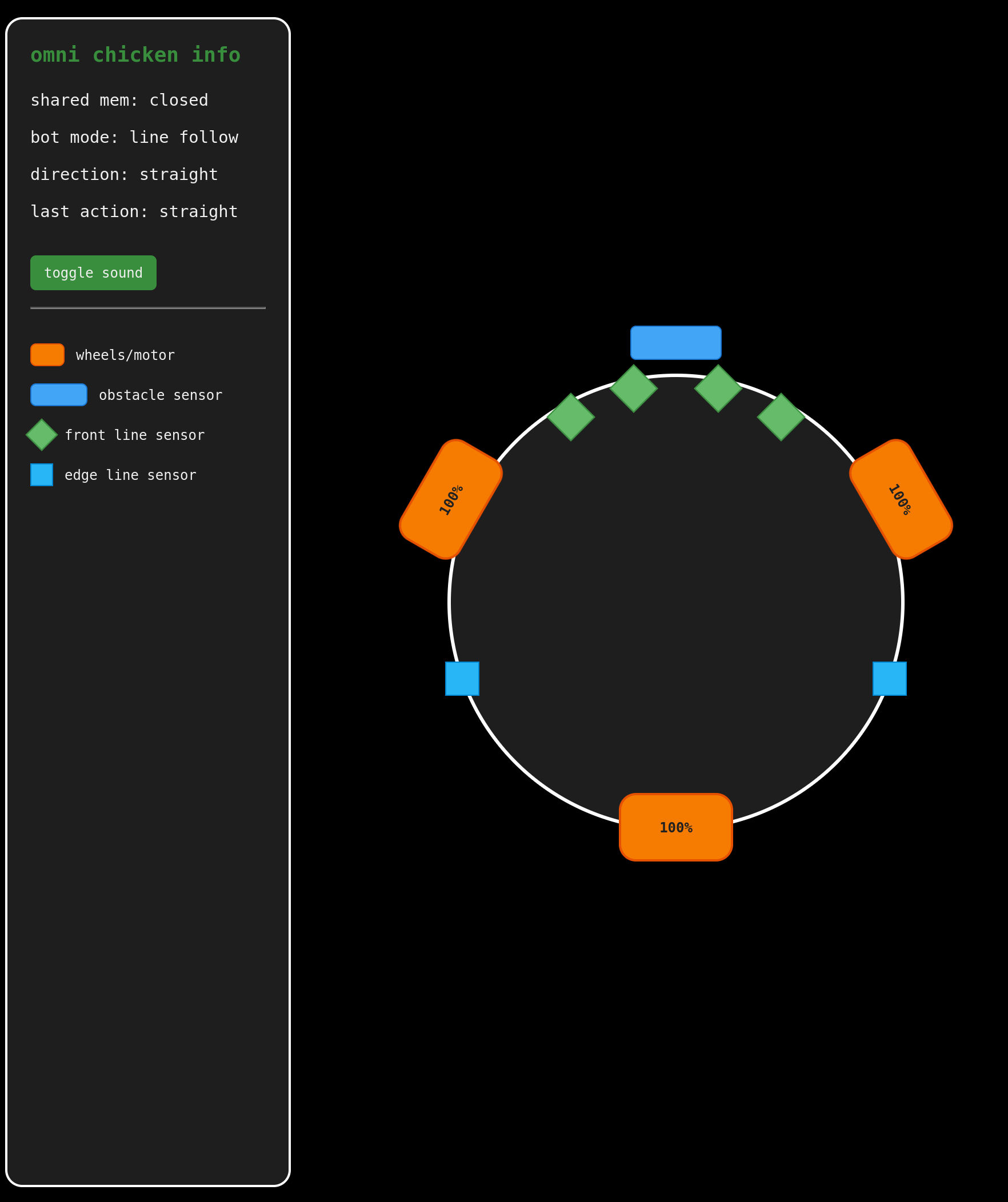
Remember the Rust web server in the architecture diagram? Yeah, so I decided to have some EXTRA bit of fun and create a web server that can monitor the status of the bot while it was running and doing bot stuff. I did a fair amount of research to try and find the most optimal way to communicate between the C program and the Rust web server. I went through the rabbit hole of ipc. From Unix sockets and message queues, the most straightforward to me was shared memory. Since it used mmap, and I've already somewhat learned about how to use mmap from my work on modifying the GPIO direct registry access library.
There's probably a more optimal way of doing shared memory, but for the sake of my sanity, I went with a simple option to just throw everything in a shared data struct to pass around. Here's what that looks like:
In C:
typedef struct {
    int ver;
    in direction;
    int motor_power[3];
    int bot_mode;
    int obstacle;
    int obstacle_mode;
    int go_left;
    int go_right;
    int sensor_mode;
    int sensors[5];
} Shared;
In Rust:
#[repr(C)]
#[derive(Debug, Clone, Copy)]
struct Shared {
    ver: i32,
    direction: i32,
    motor_power: [i32; 3],
    bot_mode: i32,
    obstacle: i32,
    obstacle_mode: i32,
    go_left: i32,
    go_right: i32,
    sensor_mode: i32,
    sensors: [i32; 5],
}
Lucky for me, shared memory on Rust is pretty straightforward, there exists a crate just for it, which I'm pretty sure uses the *nix and libc crates for Linux-specific system calls like mmap().
To read more about how the Rust side works, you can take a gander at this project post, where I go somewhat more in-depth.
Final Thoughts
This was truly an endeavour to say the least, it was arguably the most fun I've ever working on a project. Our team worked so well together and we managed to make the most unique robot that happened to also be relatively quick (thanks to the omni-directional wheels provided by Bryan). Working on this project opened a completely un-opened side of me - a love for embedded projects and robotics.
Attribution
GPIO & Hardware Interface
Raspberry Pi GPIO C DRA Example
Used as a basis for a custom GPIO C library for direct register access.WaveShare Motor Driver Hat Demo
Used for I2C communication and PWM motor control implementation.
PID Control & Motion Tuning
- Three-Omnidirectional Wheels with PID
Used as a reference for implementing PID control on a 3-wheel omni-directional robot.
Kinematics & Vector Calculations
3-wheel-omni Vectoring Arduino Example
Used as a cross-reference for omni-wheel vector calculations.Inverse Kinematics GitHub Example
Used as a basis for deriving and simulating inverse kinematics equations.
Scientific & Academic References
Evaluation of the Path-Tracking Accuracy... (MDPI, 2021)
Used for inverse kinematics ($IK$) formulae and path tracking evaluation.APR Mobile Robot Motion System (MDPI, 2016)
Referenced for derivation and explanation of the motion system used in similar omni-robots.Kinematics and Control of a 3-Wheel Omni Robot (ResearchGate)
Cross-referenced for control models and system dynamics.Appl. Sci. – Omniwheel Robot Kinematics (MDPI, 2018)
Used for further validation of omni-directional robot kinematic formulations.Movement Control of Three Omni-Wheels Robot using Pole Placement and PID (ResearchGate)
Referenced for PID and state feedback techniques applied to omni-wheeled robot motion control.Aerodynamics Study (ResearchGate)
Included for academic completeness and unique approach to aerodynamic modeling in animated figures.Path Tracking Simulation of a Robot with Mecanum Wheels (ResearchGate)
Used for simulation insights into Mecanum-style robot motion and control.SSRG IJEEE: Omni Wheel Robot Implementation (PDF)
A compact study on 3-wheel omni-directional robot design and results.Control Allocation and Tracking for Omni Robots (ScienceDirect)
A comprehensive paper on optimal control strategies for omni-directional robots.Omni-Wheel Mobile Robot Design and Control (Springer)
Technical research article discussing the design, kinematics, and control methodology of omni-wheel robots.YouTube: Aerodynamic Simulation Clip
Visual representation accompanying aerodynamic studies mentioned above.